|
|
|
|
Classic Bikes
Custom Bikes
Individual
Racing Bikes AJP
AJS
Aprilia
Ariel
Avinton / Wakan
Bajaj
Benelli
Beta
Bimota
BMW
Brough Superior
BRP Cam-Am
BSA
Buell / EBR
Bultaco
Cagiva
Campagna
CCM
CF Moto
Combat Motors
Derbi
Deus
Ducati
Excelsior
GASGAS
Ghezzi Brian
Gilera
GIMA
Harley Davidson
Hero
Highland
Honda
Horex
Husaberg
Husqvarna
Hyosung
Indian
Jawa
Kawasaki
KTM
KYMCO
Laverda
Lazareth
Magni
Maico
Mash
Matchless
Mondial
Moto Guzzi
Moto Morini
MV Agusta
MZ / MuZ
NCR
Norton
NSU
Paton
Peugeot
Piaggio
Revival Cycles
Roland Sands
Royal Enfield
Sachs
Sherco
Sunbeam
Suzuki
SWM
SYM
Triumph
TVS
Ural
Velocette
Vespa
Victory
Vincent
VOR
Voxan
Vyrus
Walt Siegl
Walz
Wrenchmonkees
Wunderlich
XTR / Radical
Yamaha
Zero
Video
Technical
Complete Manufacturer List
|
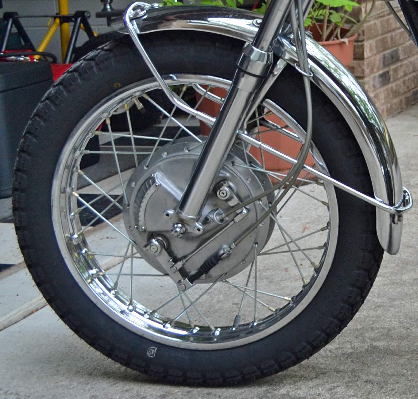
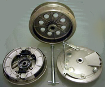
Leading shoe drum brake
The
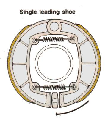
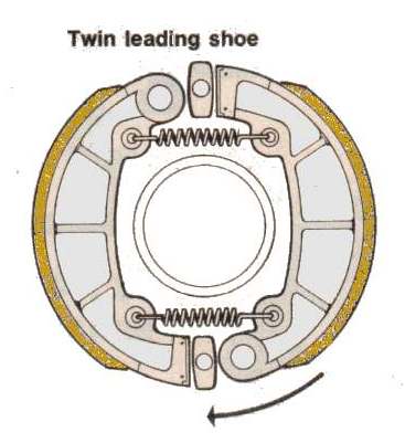
single-leading-shoe drum brake (SLS), a.k.a. "leading/trailing drum
brake", is a basic type of drum brake design.
The twin-leading-shoe brake (2LS) is a type of drum brake that has two leading shoes, rather than the single leading shoe and a single trailing shoe of a single-leading shoe (SLS) drum brake. A leading shoe has a self-servo effect, so an advantage of a 2LS is that it provides the maximum retardation in its intended direction of travel, i.e. forwards. 2LS brakes are fitted on the front axle of automobiles, or the front wheel of a motorcycle. A 2LS brake is more powerful than an SLS design.
SLS brakes are still used for the on the rear wheel of many motorcycles, and for the front wheel of smaller bikes and scooters. An SLS brake is less powerful than a TLS, but that is not an issue for a motorcycle's rear brake. Compared to cars, bike are higher and have a shorter wheelbase, so weight-transference under braking is much more pronounced. Excessive braking force can cause the rear wheel to lock, so it is normal for a bike's rear brake to be much less powerful than the front. Since 1969, modern motorcycles tend to have disc brake(s) on the front wheel, and sometimes a smaller disc brake on the rear wheel. Before disc brakes became commonplace on bikes, performance machines tended to have twin-leading-shoe drum brakes, and some racing machines even had four-leading shoe drum brakes.
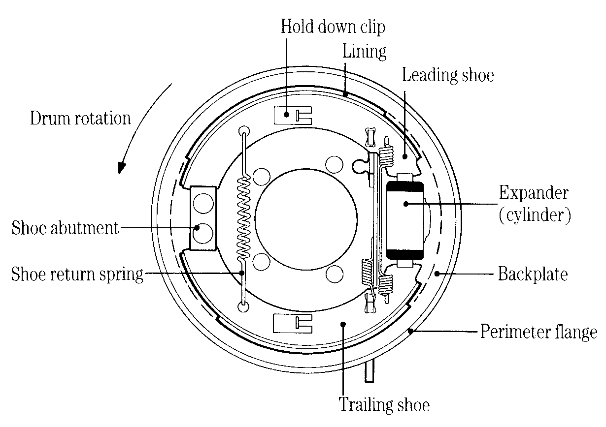
Fig 1 Let us put all the above in context.
Firstly, what is a drum brake?
A drum brake for road vehicles consists of a number of lined
shoes located within a drum that rotates with the wheel. To slow or stop the
vehicle the shoes are pressed against the inside surface of the drum to create a
friction force. Correct drum brake geometry is important in order to ensure
that:
Fig 12
Figure 1 shows a typical arrangement of the shoes and other
stationary components in a drum brake. The whole assembly is mounted on the back
plate. For clarity, only the inner surface of the drum is indicated, but in
practice its rotating outer surface is very close to the back plate perimeter
flange. The small clearance between them reduces the risk of dust, water and
foreign bodies entering the drum. The brake shoes shown in Figure 1 are forced
apart and into contact with the drum by the small hydraulic cylinder, or
expander, shown on the right. They pivot about the shoe abutment on the left and
are restored to the 'brakes off' position by the shoe return springs.
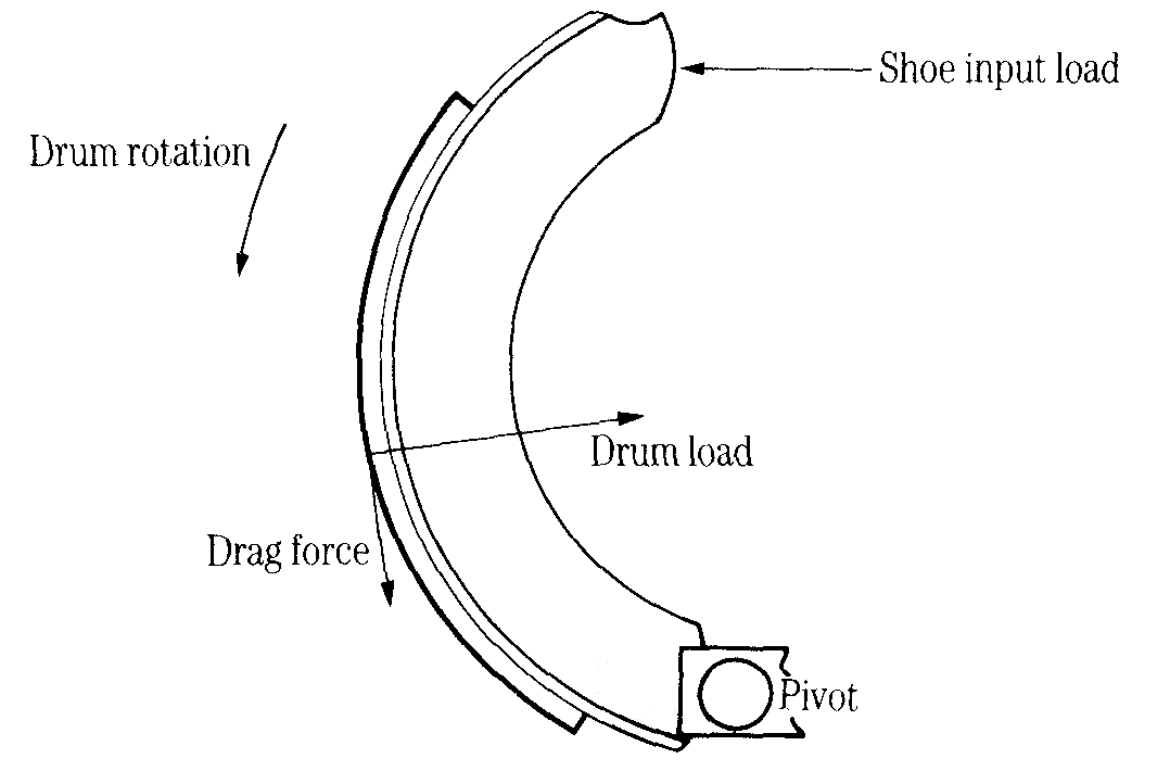
Figure 2 shows the forces acting when a leading shoe is applied. Notice that the frictional drag force has a moment about the pivot point. This increases the input load and hence increases the drag. In other words, there is a self-servo action, which increases the braking effect.
Figure 3 shows the forces acting when a trailing shoe is applied. In this case the moment of the frictional drag force about the pivot point opposes the input load, thereby reducing the drag and the braking effect.
Sources: Engineering Inspiration, Wikipedia
Fig 3
|
|
|
Any corrections or more information on these motorcycles will be kindly appreciated. |