|
|
|
|
Classic Bikes
Custom Bikes
Individual
Racing Bikes AJP
AJS
Aprilia
Ariel
Avinton / Wakan
Bajaj
Benelli
Beta
Bimota
BMW
Brough Superior
BRP Cam-Am
BSA
Buell / EBR
Bultaco
Cagiva
Campagna
CCM
CF Moto
Combat Motors
Derbi
Deus
Ducati
Excelsior
GASGAS
Ghezzi Brian
Gilera
GIMA
Harley Davidson
Hero
Highland
Honda
Horex
Husaberg
Husqvarna
Hyosung
Indian
Jawa
Kawasaki
KTM
KYMCO
Laverda
Lazareth
Magni
Maico
Mash
Matchless
Mondial
Moto Guzzi
Moto Morini
MV Agusta
MZ / MuZ
NCR
Norton
NSU
Paton
Peugeot
Piaggio
Revival Cycles
Roland Sands
Royal Enfield
Sachs
Sherco
Sunbeam
Suzuki
SWM
SYM
Triumph
TVS
Ural
Velocette
Vespa
Victory
Vincent
VOR
Voxan
Vyrus
Walt Siegl
Walz
Wrenchmonkees
Wunderlich
XTR / Radical
Yamaha
Zero
Video
Technical
Complete Manufacturer List
|
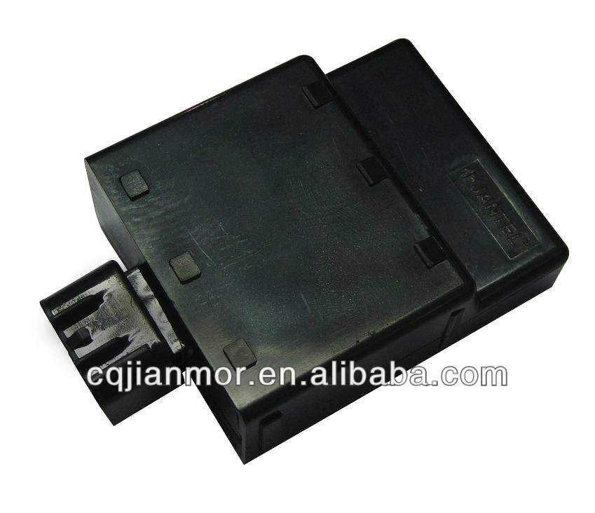
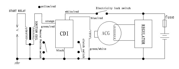
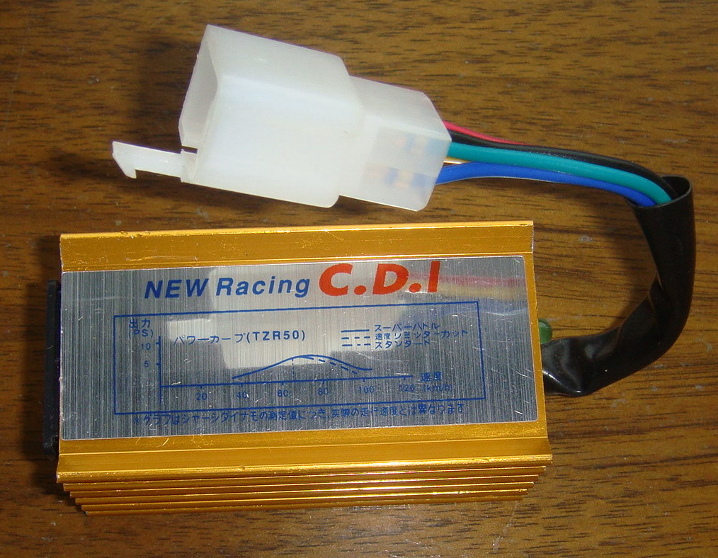
CDI - Capacitor discharge ignition
Capacitor discharge ignition (CDI) or thyristor ignition is a type of automotive
electronic ignition system which is widely used in motorcycles.
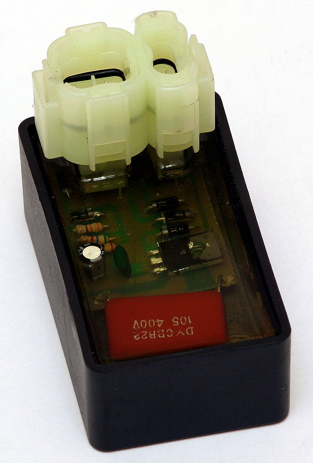
A typical CDI module consists of a small transformer, a charging circuit, a triggering circuit and a main capacitor. First, the system voltage is raised up to 250 to 600 volts by a power supply inside the CDI module. Then, the electric current flows to the charging circuit and charges the capacitor.
The rectifier inside the charging circuit prevents capacitor discharge before the moment of ignition. When the triggering circuit receives triggering signals, the triggering circuit stops the operation of the charging circuit, allowing the capacitor to discharge its output rapidly to the low inductance ignition coil. In a CD ignition, the ignition coil acts as a pulse transformer rather than an energy storage medium as it does in an inductive system.
The voltage output to the spark plugs is purely dependent on the design of the CD ignition. Voltages exceeding the insulation capabilities of existing ignition components can lead to early failure of those components. Most CD ignitions are made to give very high output voltages, but this is not always beneficial. When there's no triggering signal, the charging circuit is re-connected to charge the capacitor.
A CDI system has a short charging time, a fast voltage rise (between 3 ~ 10 kV/μs) compared to typical inductive systems (300 ~ 500 V/μs) and a short spark duration limited to about 50-80 µs. The fast voltage rise makes CDI systems insensitive to shunt resistance, but the limited spark duration can for some applications be too short to provide reliable ignition. The insensitivity to shunt resistance and the ability to fire multiple sparks can provide improved cold starting ability.
Another description: In a CDI system, the system charges a capacitor by default, and during the ignition point the system stops charging the capacitor, allowing the capacitor to discharge its output to the final coil before reaching the spark plug.
Maintaining a CDI system
Under normal circumstances, a CDI-type ignition system
requires very little attention aside from regular spark plug changes. Some
motorcycles allow for some adjustment in the ignition timing, which changes the
points at which the source and pickup coils are triggered, by using a movable
coil plate. Ideally, the pickup coil should trigger the ignition coil just
before the engine's piston reaches the top of its stroke. Moving the plate
against the flywheel's rotational direction advances the timing and creates a
spark sooner. Alternatively, moving the plate in the same direction of the
flywheel retards the timing, generating the spark later. A mark along the edge
of the coil plate will indicate the timing position relative to the position of
the piston. Adjustments to the ignition timing are not usually required unless
the motorcycle is being used for competition. Such adjustments can affect the
machine's reliability unless performed carefully.
Troubleshooting A CDI ignition System Sources: How Stuff Works, BASF
|
|
|
Any corrections or more information on these motorcycles will be kindly appreciated. |